Scaling LOAD - 200 LOAD CLIP
The older ford ECU's can only calculate up to 200 LOAD, once the ecu reaches 2.00 LOAD it cannot calculate further. This does not apply to the CAN-BUS ECU's that can be modified to calculate up to 400 LOAD. When the ECU reaches its highest calculatable LOAD it may cause the ecu to reset, enter crank mode, etc.. but most importantly you loose spark control since you will be clipping the top of the spark table, all of which are undesireable results. To compensate for clipping LOAD at 2.00 you must increase the SARCHG value (CID scalar) so LOAD is below 2.00 I typically never let LOAD get above 1.50 on most vehicles I tune that way you still have some cushion if they decided to turn it up. Keep in mind when doing this you'll need to adjust FN035 and the spark values so your not demanding excessive timing and a lean mix under boost.How to reduce LOAD ? As I mentioned before, LOAD is calcualted by airmass from the maf and SARCHG - the engine size scalar.
(FYI: SARCHG is an abbreviation of standard aircharge.)
You can reduce LOAD by simply dividing your maximum load value by your new desired maximum load value. lets say your reaching 1.75 load at WOT and you want it to be at 1.40 1.75 / 1.40 = 1.25 If you multiply SARCHG by that (lets say sarchg is at 143) 143 * 1.25 = 178, when you INCREASE sarchg to 178 your new load at WOT will be your desired 1.40 LOAD. REMEMBER: When changing SARCHG, the bigger concern will always be the spark table axis scaling as a lower load will command MORE timing all else being the same. Be sure anytime you increase SARCHG to reduce LOAD that you ADJUST THE SPARK TABLE ACCORDINGLY either by reducing the LOAD axis scaling function or by reducing the commanded spark advance for the new lower LOAD values. As not only will WOT have a lower LOAD value, the zero crossing LOAD value will be lower as well and will need to be updated in both FN035 and by making sure the commanded spark advance in the table at that zero crossing point is not excessive for the engine naturally aspirated.
Table Axis Scaling tables for BOOST (greater spark control)
The majority of EEC's do not have MAP sensor inputs, and the ones that do aren't boost friendly, so we can't adjust timing based on boost right? WRONG!!Again, this write up pertains to MASS AIR ecu's, using the MAF you can rescale the tables axis to retard timing based off of boost pressure (higher loads).
The only reason you would rescale the tables axis is to get more control of spark so you can demand a different value at higher loads that a stock engine doesn't need to have access to since it cannot reach those higher loads naturally aspirated. Henry didn't scale table axis for high loads for the simple fact that the stock engine can't reach those loads so they put more resolution down low. Typically a stock 302 only reaches ~75 load around 4k and load falls above and below 4k (peak torque).
So for example, let say at WOT your setup with 6 psi of boost puts you at 1.20 load, with 10 psi your at 1.50 load and at your max boost of 18psi your at 1.80 load, you can rescale the tables so you can control timing and fuel at these boost levels.
Now this is all assuming the wot spark functions are disabled (for older eec-iv's), and if your strategy doesn't have that hack added to it you can set the tps breakpoint for WOT to its maximum value so the WOT flag will never be set. The only downfall is that by doing that you loose the WOT multiplier functions, but its not very common that you would need to use those functions anyway, just keep that in mind if you go that route so when you look at your logs your APT (throttle state) will never reach 1 (1=WOT). The WOT spark functions were probably incorporated in the ecu's as a safety measure in the older ecu's, but ideally you don't want to pull spark just because the pedal is through the floor, you want to 'ramp' spark which will increase torque, throttle response, fuel economy, etc... which is how the newer ecu's control spark from the factory, plus it allows you to add or remove boost without having to change calibrations.
See the Simplify Fox Timing Write Up for more details.
NOTE: With the WOT breakpoint set to maximum, while cranking with the throttle pedal to the floor to normally activate the flood-clear "kill injector" mode, it will not function since the ecu will not recognize WOT.
I recommend everyone to use only one spark table just for the sake of keeping everything simple, the only people that may want to interpolate between the lug tables would be those who have a very high compression engine running low octane fuel or those advanced tuners with manuals behind turbo's trying to decrease spool after a shift. Most 94 and later ecu's use the least amount of calculated spark at any given time if you have a newer ecu you can set all other spark tables to high values ~60 and just use the borderline knock table as your primary means of spark (don't forget about the multiplier tables and functions), if you have a GUFX ecu then just set the hack scalar for spark inhibit to sealevel only or just download the A9L2 Base Tune
For more ignition timing information visit the TIMING Write Up and the MBT reference chart.
...now on to the good stuff...
Nomalizing - Axis Scaling Functions
This example given is specifically for the Sealevel Spark table in GUFX, however, the FN2200 Borderline Knock table in newer ecu's follows the same principles as do all tables axis scaling.FN904A is the Sealevel Spark Table in older EEC-IV, the Y-Axis is Normalized Load Scaled from FN071
So off to function FN071 we go
FN071 - Stock A9L:
As always the X-Axis top most and bottom most values should never be changed under any circumstances in any function. 200/400 is the max LOAD the ecu can calculate and 0 is the least LOAD, the value in the Y-Axis is the row for the table its scaling.
I know to some that's got to be confusing so I'll break it down and make it nice and easy to understand by going through it
If you cruise back up or if you have a high enough resolution display setting on your monitor you'll see that i put the row numbers next to the sealevel load table scaling so you can understand where each point is referencing, but if you don't,
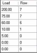
here it is again in bold, the values on the left are the Y-axis input for the Spark Sealevel Table
75 (row 7)
60 (row 6)
50 (row 5)
40 (row 4)
30 (row 3)
20 (row 2)
10 (row 1)
5 (row 0)
Which is the same thing as this
We'll take it from the bottom, from the load scaling of FN701, anything from 0 to 5 load is using row 0, then 10 load is right there in the function at row 1 so no interpolation is being done, the next value is 60 at row 6, so the ecu is interpolating everything in between. 60 -10 = 50, 6 - 1 = 5, 50 / 5 = 10 per row, so row 2 is row 1 + 10, row 3 is row 2 + 10, and so on, row 7 is 75 to 200. So everything from 75 load and greater (up to) 200 load uses row 7. This is how all scaling functions 'function' in the ecu.
Now its up to you to change your spark scaling to better suit your needs, pretty much everything 30 load and less (actual unscaled load) can use the same timing normally, at CT and Idle, spark is being called out from FN111, so everything below about 20 load will just about never be used. With that knowledge right off the bat you can free up 3 rows right there which may be enough to do what you need to. if not then you can adjust accordingly. I highly recommend the spark scaling I have in the A9L2 and T4M2 Base Tunes for all calibrations.
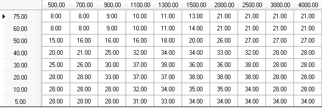
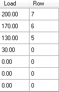
Now with the original load scaling i made for my theoretical engine example, i would scale the spark table to something like this:
Which made my spark table look like
Be sure you save the calibration when changing any scaling function for those changes to be applied, else it will show the scaling it was loaded with. Don't forget YOU ALSO NEED TO ADJUST ALL THE TABLES AND FUNCTIONS THAT THE NEW SCALING CHANGES. LOOK IN THE COMMENTS FOR AN IDEA OF WHERE TO ADJUST EVERYTHING ELSE.
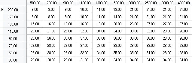
You can now plug in the timing you want at each point of boost and enjoy the new powah and voila! Now we have table scaling for boost.
Here is a quick example of what an optimized timing table might look like just to give you an idea:
Load is going to vary per setup, load is based off airflow and CID, since we all run different MAF's and using the maf to dial in fuel is a typical method. Load can be anywhere at any time on any setup, can't really say where its going to be unless you have a flowed or known MAF curve.
See the Spark Write Up for more details on ignition timing. The MBT Reference Chart can be found on the home page under reference.
I recommend giving the Tips & Tricks Write Up a read over for various ways to force open loop, disable hego2, etc...
Return Home
Jump to Forum